Edges: What to Specify for Accurate Quotes & Reliable Parts
Edges are where real‑world manufacturing meets the ideal CAD model. After machining, cutting, stamping, or printing, parts often have sharp corners and burrs. Edge specifications tell the supplier whether to leave an edge sharp, apply a defined geometry (e.g., a chamfer or radius), or control “undefined” edge conditions (e.g., permissible burr/undercut) — which directly affects fit, safety, and cost.
Why it matters
• Incorrect or missing edge specs create rework, scrap, injuries (handling), and assembly issues. • Over‑specifying (e.g., tiny chamfers everywhere) inflates cost and lead time. • Clear, global rules (plus explicit exceptions) reduce back‑and‑forth and inspection ambiguity.
Key Terms (plain‑English)
- Burr — Excess material protruding from an edge after cutting or machining. Usually removed or limited.
- Edge break — Light removal to blunt a sharp corner; can be a small chamfer or radius, often given as a range (e.g., Break all sharp edges 0.2–0.5).
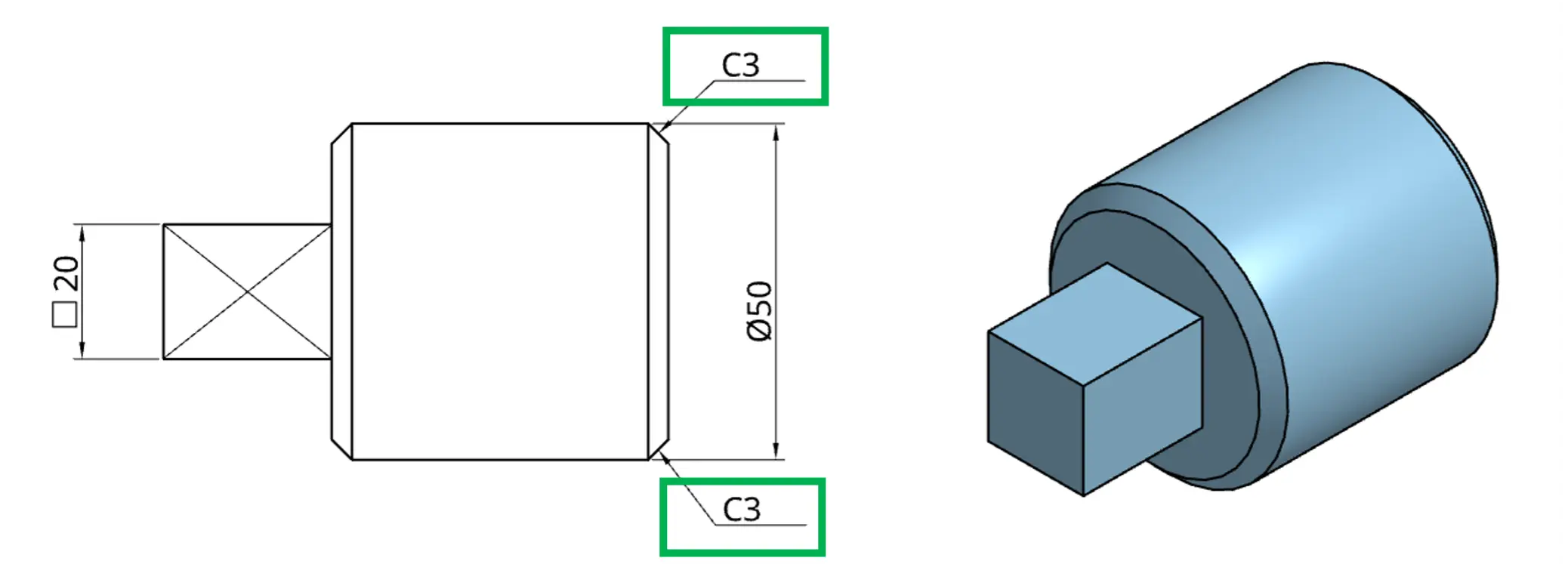
- Chamfer — A straight, slanted cut that replaces the sharp corner. Often at 45°; specified by size × angle (e.g., 0.5 × 45°) or C‑value at 45° (e.g., C3).
- Radius / Fillet — A curved replacement for the sharp corner (e.g., R0.5). Fillets are internal; rounds are external.
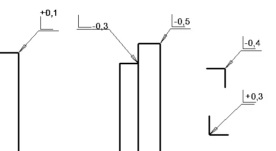
- Undefined edge — An edge whose final contour is not strictly geometric (no explicit R or chamfer); instead, a limit on passing/burr or undercut is specified (ISO style).
Standards at a Glance
- Defined shapes (e.g., 1 × 45° chamfer, R0.5): use standard dimensioning practices.
- Undefined edges (allowable burr/undercut): use the ISO edge symbol with + / − / ± and a size.
- Global vs. local: You can give a general rule for all edges and then call out exceptions at specific features.
Werk24 note: We normalize both ISO and ASME‑style drawings. Whether your drawing says C0.5, 0.5 × 45°, Break edges 0.2–0.5, or uses the ISO edge symbol, we return consistent, typed fields for downstream systems.
How to Read Common Edge Callouts
1) Chamfers
45° shorthand (C‑value)
C3→ Chamfer width 3 mm at 45°.2X C1.5→ Two edges, each 1.5 mm × 45°.
General form (size × angle)
0.5 × 45° CHAM→ Chamfer 0.5 mm at 45°.0.8 × 30°→ Chamfer 0.8 mm at 30° (make clear which face the angle references if ambiguous).
Inspection tip For small chamfers, use gauge blocks/visual comparators or CMM edge extraction with agreed tolerance (e.g., ±0.1 on leg length for non‑critical edges).
2) Edge Break / Deburr Notes
Break all sharp edges 0.2–0.5→ Remove sharpness with a small chamfer or radius; any value in the range is acceptable.Remove all burrs/Deburr→ Eliminate burrs; implies minimal edge break (often shop default).- Prefer ranges for non‑critical edges (e.g., 0.2–0.5) to avoid unnecessary cost.
3) ISO “Undefined Edge” (burr/undercut control)
Use the ISO edge symbol with:
+ a→ Passing allowed up to a (e.g., small burr/flash).− a→ Undercut allowed up to a (material locally missing below the ideal).± a→ Either passing or undercut up to a (requires a size).- Add a direction arrow if the allowance is one‑sided; apply globally or to individual edges/limited areas as needed.
Example patterns
| Pattern | Meaning | Typical Use |
|---|---|---|
+0.2 | External burr/flash permitted up to 0.2 | Laser/punch edges, castings |
−0.1 | Internal undercut permitted up to 0.1` | Milled pockets, drilled breaks |
±0.2 | Either burr or undercut up to 0.2 | Mixed processes / economical finish |
| (general note with symbol) | Applies to all edges, unless locally overridden | Fast, unambiguous spec |
Cost & Quality Tips
- Default wisely: If you use a global rule (e.g., Break all sharp edges 0.2–0.5 or ISO edge symbol ±0.2), list exceptions for critical sealing edges or aesthetic faces.
- Group by process/face: Deburring accessibility drives cost. Combine similar edges and avoid per‑edge micro‑specs unless functional.
- Material & process matter: Punching, laser cutting, and hard alloys produce larger burrs → plan allowances accordingly.
- Functional edges: For edges that locate, seal, or mate, use defined chamfers/radii with tolerances rather than vague “break edge”.
What Werk24 Detects & Normalizes
We parse and standardize edge information across ISO/ASME and multiple languages. Returned fields typically include:
- type:
chamfer|radius|edge_break|iso_edge - amount: numeric size or range (e.g.,
0.2–0.5,3.0) - angle: degrees for chamfers (if present)
- scope: global note, per‑edge count (e.g.,
2X), or feature reference - polarity (ISO edge):
+/−/± - direction: if one‑sided indication is present
- phrase: original note snippet for traceability
This lets your ERP/MES/PLM downstream consistently price deburring, edge‑rounding, inspection, and exceptions.
Examples (ready‑to‑use)
- Global rule (economical): Break all sharp edges 0.2–0.5, except sealing edge A remains sharp, burr ≤ +0.05.
- Defined geometry (critical seating): C1.0 × 45° on Ø80 counterbore mouth.
- ISO undefined edges (laser‑cut plate): All edges: ±0.2; outer profile: +0.3 max; slot S1: −0.1 max.
Chamfer Dimension (quick refresher)
A chamfer defines the size of the slanted edge and its angle. Two common notations:
- C‑value at 45° —
C3→ width 3 mm, angle 45°. - Length × angle —
0.5 × 45°(or other angles:0.8 × 30°).