GD&T: What You Need to Know to Quote Profitably
Geometric Dimensioning & Tolerancing (GD&T) specifies the allowed 3D variation of features so parts assemble and function correctly. Think of it as precision in space: not just “size,” but shape, orientation, and location—often relative to datums (reference frames).
Drawings with tight GD&T drive cost (setups, fixtures, CMM time, scrap risk). Ignoring GD&T leads to under-quoting or non-conforming parts. This page gives you a fast, practical lens to assess risk and price correctly.
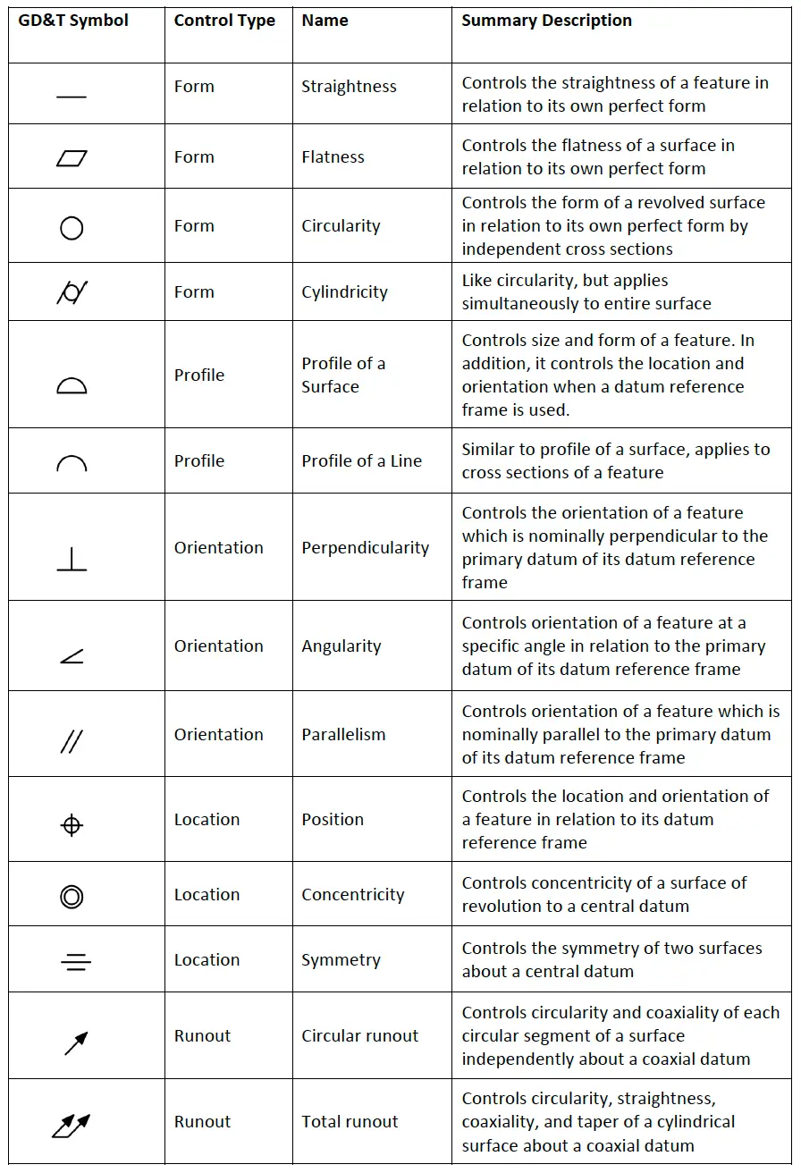
Why GD&T matters for quoting
- Tighter zones = higher price. Sub-0.05 mm position, flatness, or runout on medium/large parts almost always needs precision fixturing and CMM time.
- Datums drive setups. More datums and stricter orientation controls usually mean more setups or complex fixtures.
- Modifiers change the game. MMC/LMC can increase the usable tolerance in production (bonus tolerance)—or, without them (RFS), hold you to the worst case.
Reading a Feature Control Frame (FCF)
An FCF is read left → right:
- Characteristic symbol (e.g., position ⌖, flatness ▱, perpendicularity ⟂)
- Tolerance value (Ø if cylindrical zone) + optional modifiers (M, L, S)
- Datums in order (primary, secondary, tertiary) + their modifiers if present
Example (text form): POSITION | ⌀0.10 | M | A | B(M) | C → A cylindrical positional zone Ø0.10 at MMC, oriented/located to datums A, B at MMC, and C.
Datums (your measurement anchor)
A datum is a theoretically exact reference (plane/axis/point). Production and inspection “lock” the part to primary → secondary → tertiary datums to define 6 degrees of constraint.
- Datum feature vs datum: The machined surface/bore is the feature; the ideal plane/axis derived from it is the datum.
- Targets & partial datums: Complex shapes may use datum targets or limited areas.
- Shifting datums: With M on a datum reference (e.g., B(M)), the fixture/inspection may allow controlled shift—often reducing scrap.
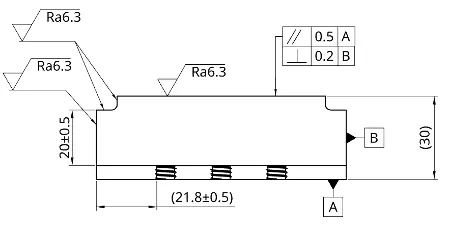
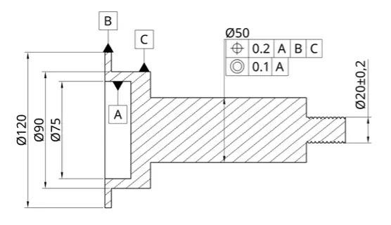
Here, A and B are the datums used to control other features:
The core GD&T characteristics (what they really do)
Form (no datums): controls shape of a single feature
- Straightness – axis/line straight.
- Flatness – surface lies within two planes.
- Circularity (Roundness) – each section round.
- Cylindricity – cylinder straight/round along its length.
Orientation (needs datums): aligns a feature to your reference frame
- Parallelism – constant angle (0°) to a datum.
- Perpendicularity – 90° to a datum.
- Angularity – specific angle to a datum.
Location (needs datums): puts features in the right place
- Position (⌖) – 2D/3D zone for holes/pins/slots; most common cost driver.
- Concentricity/Symmetry – rare in modern practice; prefer Position or Runout where possible (easier to inspect).
Runout (needs axis/rotation): controls wobble under rotation
- Runout – per-revolution variation at a point.
- Total runout – variation along full length/area.
Profiles: shape envelopes for complex surfaces
- Profile of a line/surface – tightly controls freeform/contoured shapes; can explode CMM time if small.
Modifiers that change cost (and capability)
- MMC (M) – Maximum Material Condition. Allows bonus tolerance as the feature departs from MMC (e.g., a hole gets larger).
- LMC (L) – Least Material Condition. Opposite of MMC; useful for wall thickness/strength.
- RFS (S or implied) – Regardless of Feature Size. No bonus—hardest to hit.
- Projected tolerance zone – required for studs/holes that will carry fasteners through a thickness; prevents assembly interference.
- Datum at MMC/LMC – can permit datum shift, easing inspection/fixturing.
Quoting tip: MMC on position for holes often saves cost (gaging possible, more pass-through in production).
Patterns and composite controls
Pattern of holes: a single FCF can control all holes together.
Composite position (two stacked segments):
- Top segment – location/orientation to A|B|C (looser).
- Bottom segment – refines pattern spacing/orientation (tighter) without re-locating to A|B|C. This is powerful for assemblies: you get functional fit and manufacturable tolerances.
Practical quoting checklist
- Any position/flatness/runout ≤ 0.05 mm? Flag as precision; plan CMM and fixture time.
- RFS everywhere? Expect tighter controls → higher costs/scrap risk.
- No datums or ambiguous datums? Ask for clarification; unclear setups = rework.
- Profiles on large/freeform surfaces? Estimate significant CMM programming time.
- Projected zones for fastener stacks? If missing, clarify before build.
- Material/process fit: Can the specified tolerance be met with the proposed process (e.g., laser cut vs ream & bore)?
How Werk24 helps (ASME + ISO, any language)
Werk24 reads GD&T across ASME and ISO styles and returns a normalized, typed JSON so your ERP/MES/PLM can act on it—independent of the standard or drawing language (German, English, Spanish, Dutch, Japanese, Italian; others on request).
We extract and normalize:
- Feature Control Frames (characteristic, value, Ø, modifiers, datum stack)
- Datums & datum targets (primary/secondary/tertiary, with modifiers)
- Pattern membership and composite vs single-segment callouts
- Projected zones and material condition impacts (bonus tolerance potential)
- Cost drivers (tight zones, RFS usage, heavy profile coverage)
Use this to auto-flag risky parts, estimate inspection effort, and price confidently.
Terms you’ll see, in plain words
- Bonus tolerance: Extra tolerance gained when using MMC/LMC and the actual size departs from the material condition.
- Virtual condition: Boundary combining size + GD&T at MMC; drives functional gage design.
- CMM time: Programming + cycle time to verify GD&T; often the hidden cost.