Symbols: Read Them Right, Avoid Costly Misunderstandings
Symbols compress a lot of meaning into very little space on a technical drawing. Reading them correctly avoids ambiguity in quoting, machining, inspection, and assembly.
Tip: Units follow the drawing standard in the title block. Unless specified otherwise, ISO drawings are typically in mm. US‑centric drawings often use in.
Quick reference
| Symbol | Meaning | How to read | Example |
|---|---|---|---|
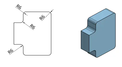
| R | Radius (arc/fillet/round) | Value is the distance from arc center to surface | R6 → radius 6 mm |
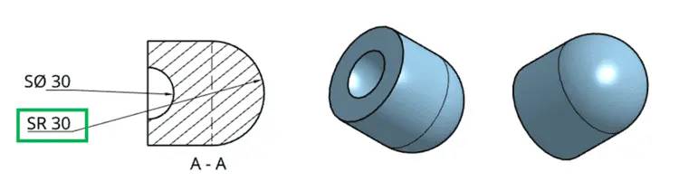
| SR | Spherical radius | Radius of a spherical surface | SR30 → spherical radius 30 mm |
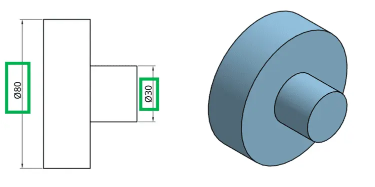
| Ø | Diameter (circle/cylindrical feature) | Value is full diameter | Ø80 → diameter 80 mm |
| SØ | Spherical diameter | Diameter of a spherical cap/surface | SØ30 → spherical diameter 30 mm |
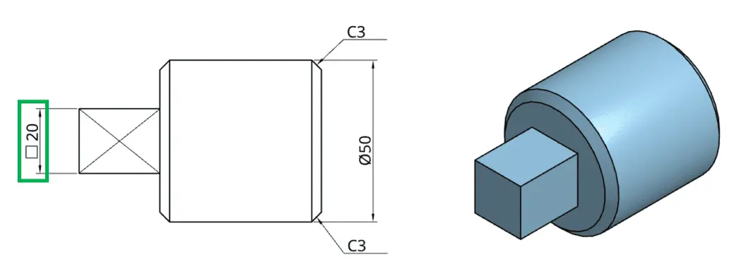
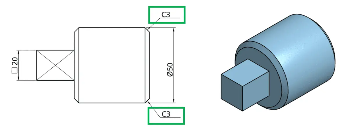
| □ | Square section | Cross‑section is square; value is side length | □20 → 20 mm × 20 mm square |
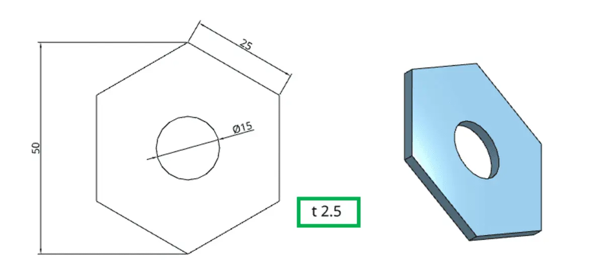
| t | Thickness (sheet/plate) | Material thickness; often used for sheet metal | t2.5 → thickness 2.5 mm |
| C | 45° chamfer shorthand | Width at 45° (default). Other variants may state angle explicitly | C3 → 3 mm × 45° chamfer |
Core symbols and best practices
Radius R
Radius is used for inside fillets and outside rounds, as well as for general arcs.
- How it’s shown:
R<value>before the dimension. - Good to know: If the entire circle is controlled, use Ø instead of R.
- Example:
R6means the radius is 6 mm.
Common pitfalls
- Calling out a radius where a full diameter is intended → use Ø for circles.
- Omitting the number of instances when multiple identical radii exist → add
(xN)if needed, e.g.,R3 (x6).
Spherical radius SR
Used when the feature is part of a sphere described by its radius.
- How it’s shown:
SR<value> - Example:
SR30→ spherical radius 30 mm.
Common pitfalls
- Confusing SR (spherical radius) with SØ (spherical diameter). Make sure the requirement matches your tooling/inspection plan.
Diameter Ø
Used for circles, cylinders, holes, and pins.
- How it’s shown:
Ø<value> - Example:
Ø80→ diameter 80 mm. - Metric vs imperial: You may see
Ø0.500 inorØ12.7depending on the standard.
Common pitfalls
- Leaving off tolerances for critical fits (e.g., bearings, shafts). Consider adding fit class (e.g.,
Ø20 H7).
Spherical diameter SØ
Used for spherical features specified by diameter.
- How it’s shown:
SØ<value> - Example:
SØ30→ spherical diameter 30 mm.
Common pitfalls
- Selecting SØ when the mating spec expects SR. Align symbols with the measuring method.
Square □
Indicates a square cross‑section.
- How it’s shown:
□<side> - Example:
□20→ 20 mm square bar. - Variations: You may also see length appended for stock, e.g.,
□20 × 100(square bar 100 mm long).
Thickness t
Common in sheet‑metal and plate parts.
- How it’s shown:
t<value> - Example:
t2.5→ material thickness 2.5 mm. - Note: Some standards use
sfor thickness; follow the title‑block convention.
Common pitfalls
- Forgetting that bend deductions/allowances depend on t. Ensure CAM settings match the material and tooling.
45‑degree chamfer C
Shorthand for a chamfer at 45° unless otherwise stated.
- How it’s shown:
C<width>or explicitly with angle:<width> × 45°. - Example:
C3→ 3 mm chamfer at 45°.
Common pitfalls
- Assuming 45° when a different angle is required. If angle matters, write it:
2 × 30°.
Quality & communication tips
- Declare units once (title block or note) and only annotate when deviating.
- Be explicit about counts for repeated features (e.g.,
R2 (x8)around a bolt circle). - Add tolerances for fit‑critical diameters and radii.
- Match symbol to inspection: choose
SRvsSØbased on how the feature will be measured.