Tolerances: Need to Know to Reduce Assembly Challenges
Tolerances define the acceptable variation on a dimension. They communicate how precise a feature must be to ensure parts fit, function, and assemble correctly—without unnecessary cost.
Ignoring tolerances leads to assembly problems, scrap, and inflated machining time. Below are the essentials that help you make better trade-offs and quote confidently.
At a Glance
- Lower IT grade number ⇒ tighter tolerance ⇒ higher cost/time.
- Fits (hole/shaft systems) specify intended clearance or interference at assembly.
- General tolerances (ISO 2768) cover untoleranced dimensions—pick one class per drawing.
- Deviation styles: bilateral, unilateral, limit, single-limit, reference, basic (TED).
- Avoid tolerance stack-ups: prefer datums and basic dimensions with GD&T.
IT Tolerance (ISO 286)
IT grades are standardized tolerance widths that scale with nominal size. They let you express “how tight” a dimension is with a single code (e.g., IT6, IT7, IT10).
- Range: commonly IT01, IT0, IT1 … IT18 (lower = tighter).
- Meaning: each IT grade corresponds to a tolerance width computed from a unit i; the width grows with nominal size.
- Rule of 10: approximately every five IT steps increase the tolerance width by ×10 for the same size range (e.g., IT7 → IT12).
Tip Use IT grades to quickly estimate manufacturing effort. Moving from IT7 to IT10 can slash machining time and cost if the function allows it.
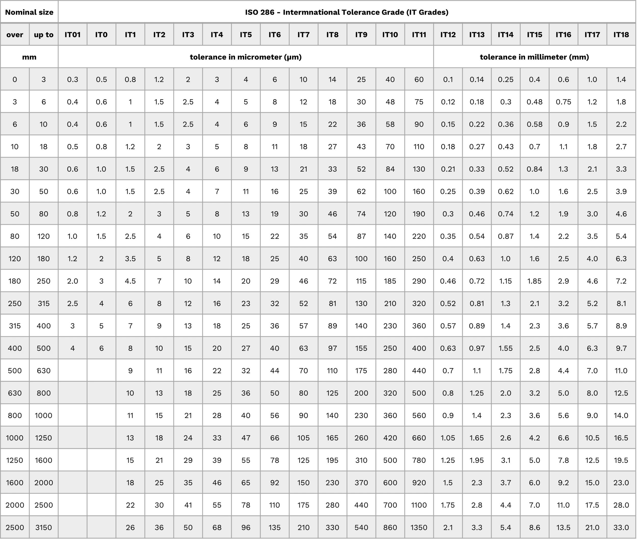
Extrapolating beyond IT18
ISO 286 formally covers basic sizes up to 3150 mm. For rough scoping beyond tables, the ×10 per five grades trend can be used to estimate (not certify) values (e.g., IT20 ≈ IT15 × 10 for the same nominal range).
Fits and Tolerances (Hole/Shaft System)
A fit is the relationship between a hole and a shaft after manufacturing, determined by their limits and deviations.
Three basic fit types
- Clearance fit – shaft always smaller than hole → free movement.
- Transition fit – may clear or interfere → precise location.
- Interference fit – shaft always larger than hole → press fit.
Letters & cases
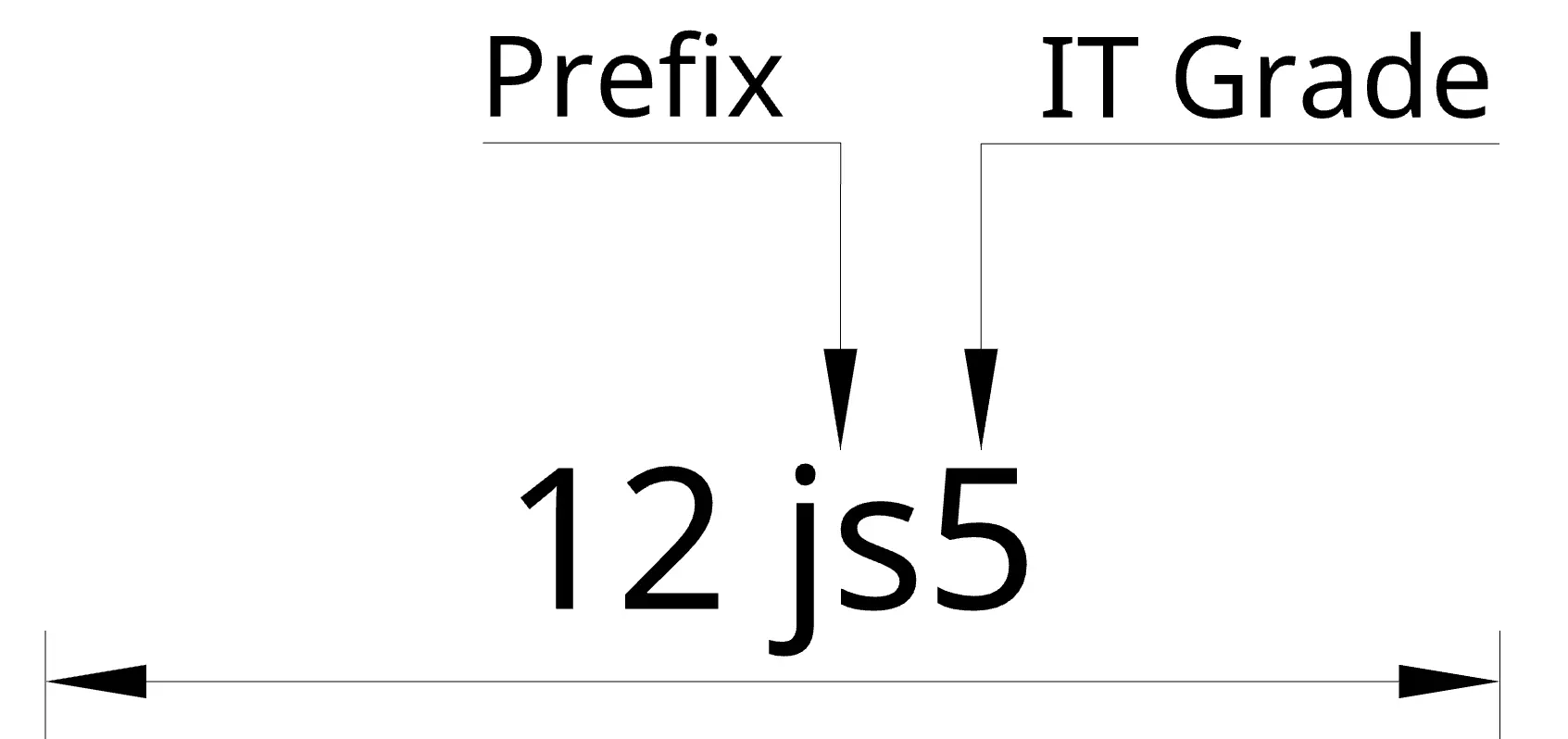
Uppercase letters (A…ZC) = holes; lowercase (a…zc) = shafts.
H/h are common: fundamental deviation is zero on the side at the nominal:
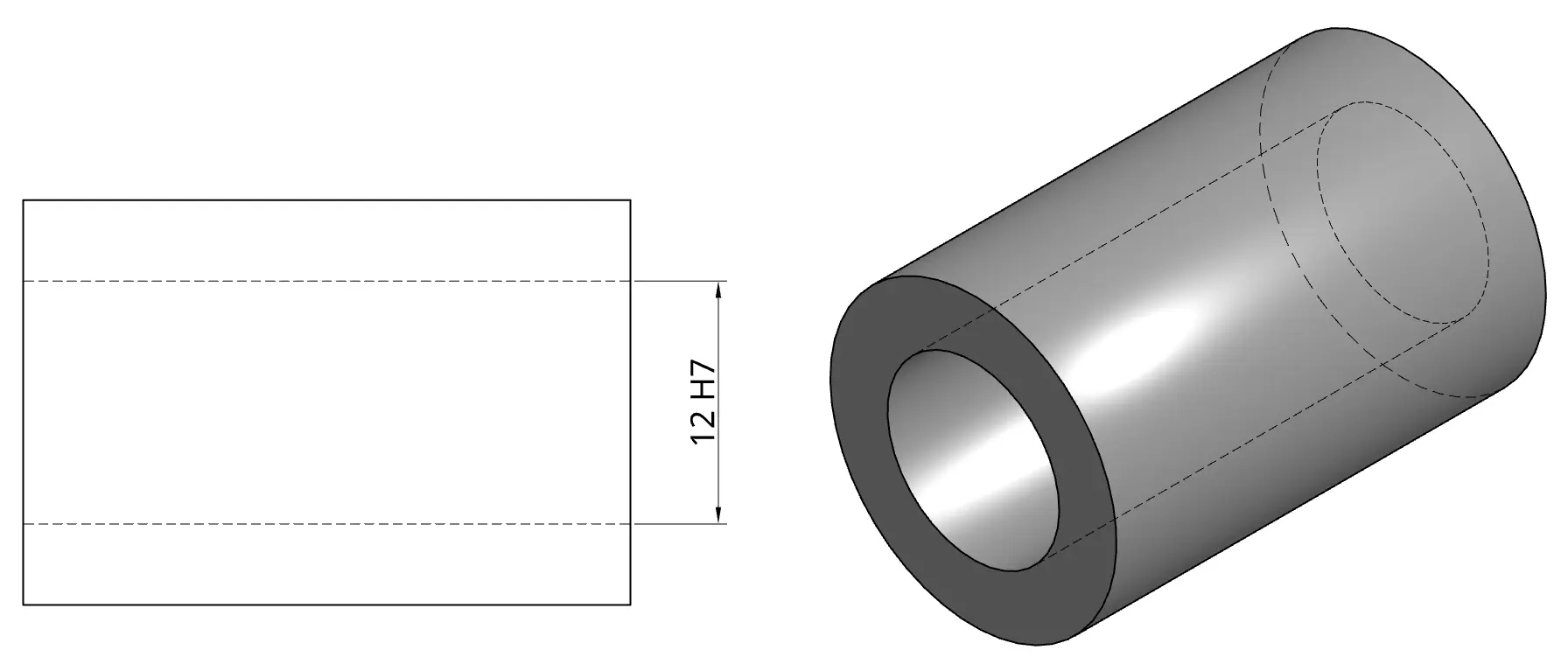
- H hole: tolerance sits above nominal (EI = 0).
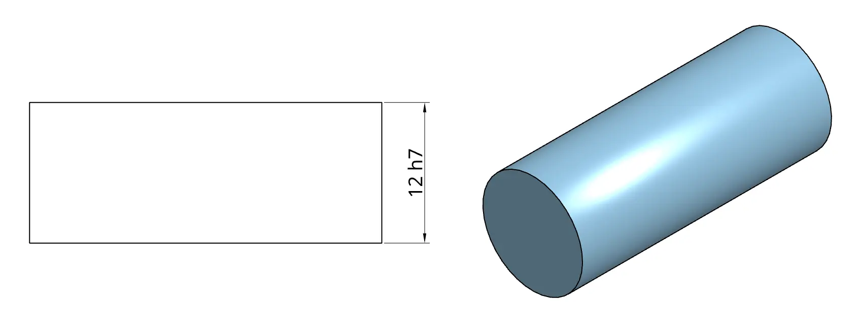
- h shaft: tolerance sits below nominal (es = 0).
JS/js = symmetric about nominal (often used where true symmetry is required).
Example (conceptual)
- 12 H7 → limits: $12.000$ up to $12.000 + IT7(Ø12)$ mm
- 12 h7 → limits: $12.000 - IT7(Ø12)$ up to $12.000$ mm
- 12 H7/g6 → typical sliding clearance fit
- 12 H7/p6 → typical interference press fit
Formula reminders
- Tolerance width $T = \text{Upper} - \text{Lower}$
- Minimum clearance = Hole$\text{min}$ − Shaft$\text{max}$
- Maximum clearance = Hole$\text{max}$ − Shaft$\text{min}$
- Interference if Minimum clearance < 0
General Tolerances (ISO 2768)
When no individual tolerance is specified, ISO 2768 applies to the dimensions it covers.
- Part 1 (ISO 2768-1) – linear & angular dimensions (without individual tolerances). Classes: f (fine), m (medium), c (coarse), v (very coarse).
- Part 2 (ISO 2768-2) – geometrical tolerances for features (straightness, flatness, etc.).
Choose one class per drawing to avoid conflicts (e.g., ISO 2768-m).
Applies to (when not individually toleranced):
- Linear dims (external/internal sizes, diameters, distances, chamfers, radii)
- Angular dims
- Linear/Angular dims created by machining of assembled parts
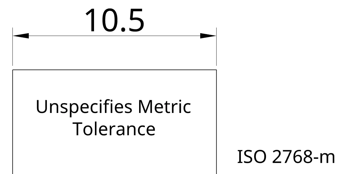
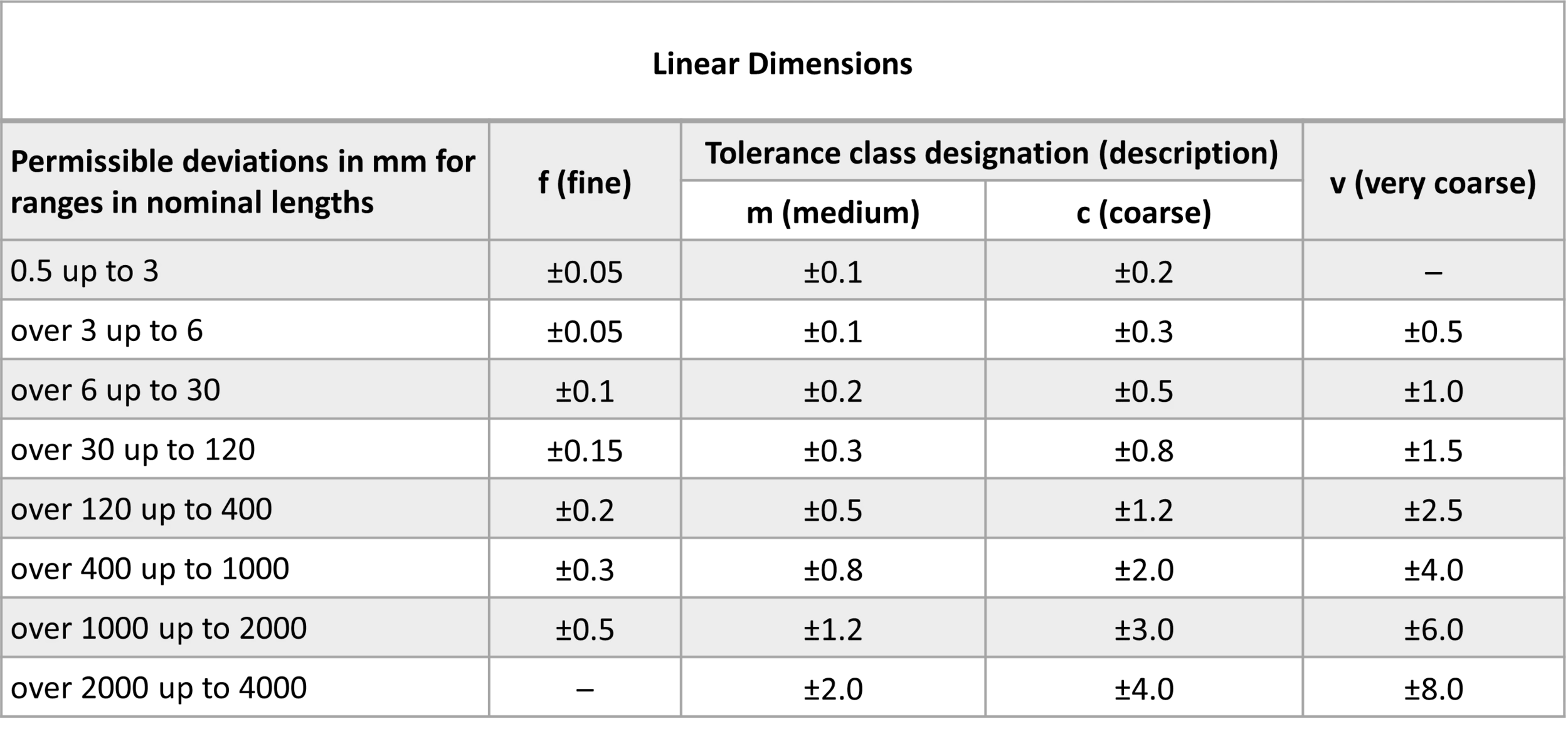
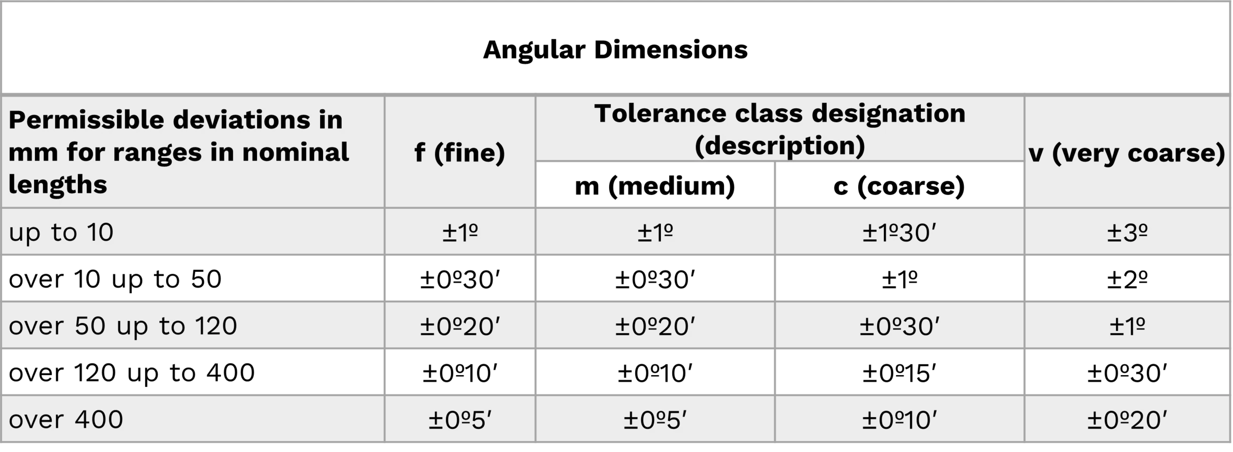
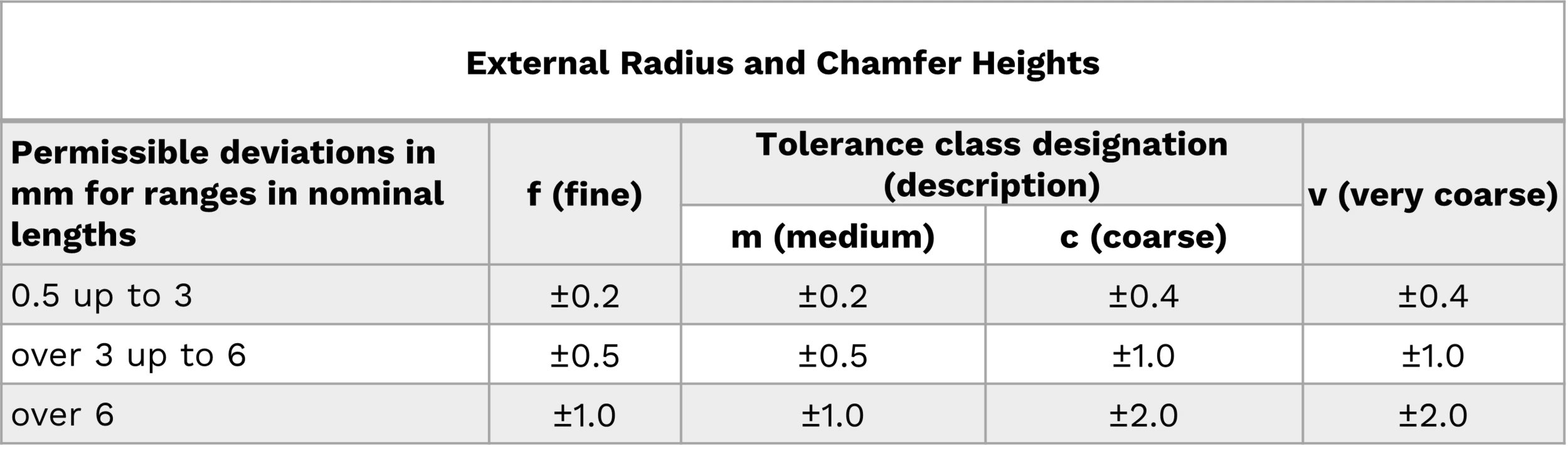

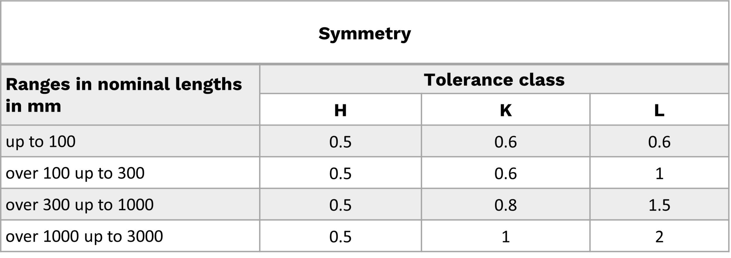
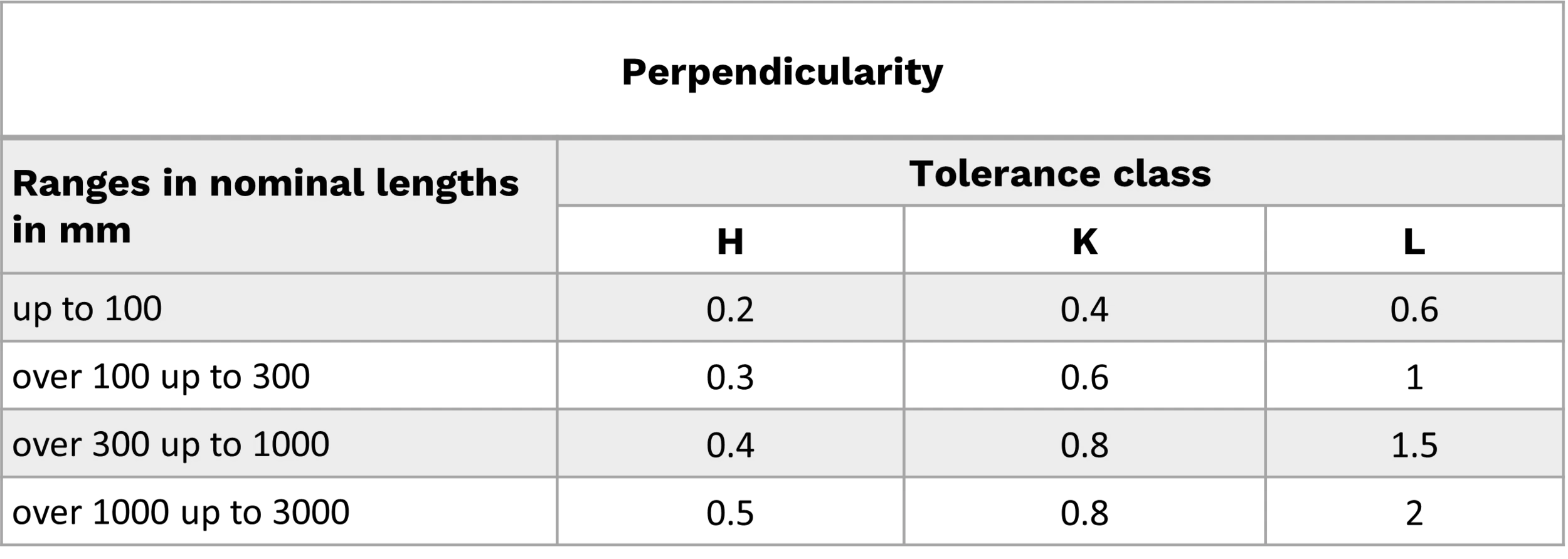
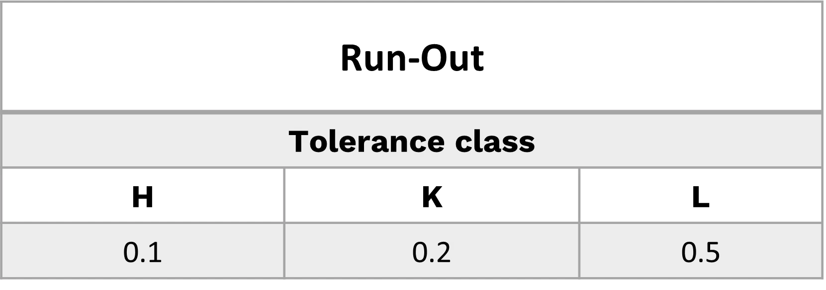
Tip Set the general tolerance once in the title block or notes (e.g.,
ISO 2768-mK), then only tighten critical features individually.
Deviation (±) Tolerancing Styles
Bilateral tolerance
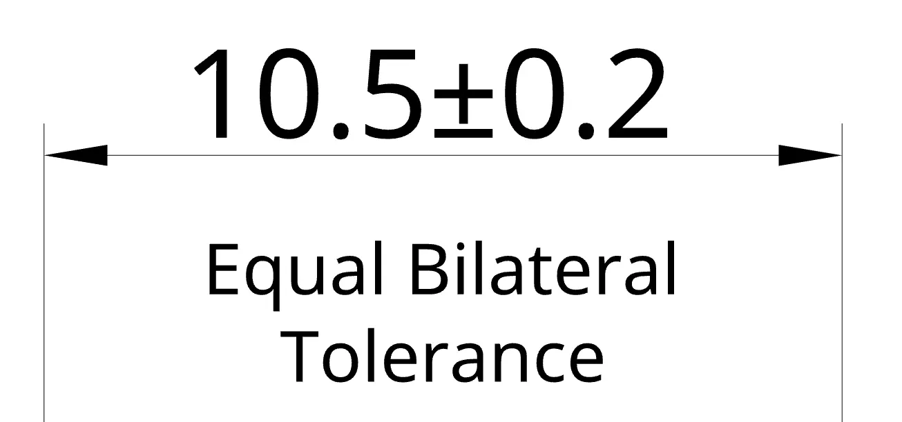
Allowed to vary both above and below nominal.
- Equal:
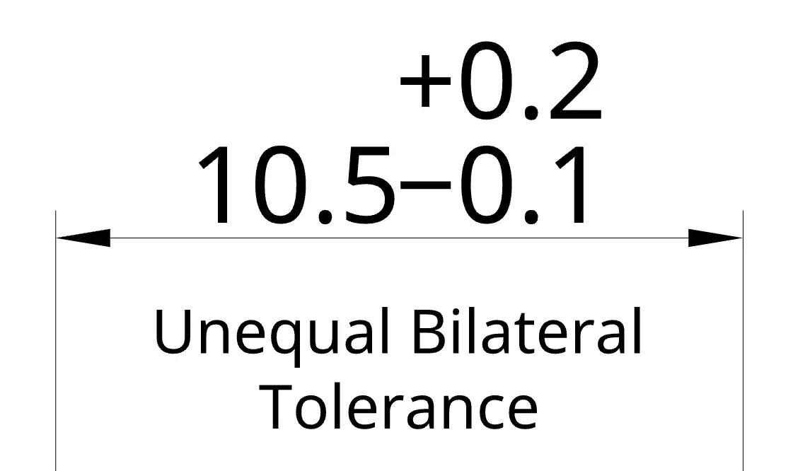
10.5 ± 0.2 - Unequal:
10.5 (+0.2/-0.1)
Unilateral tolerance
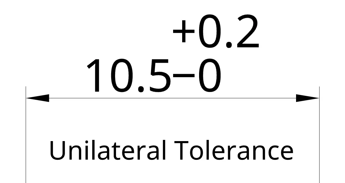
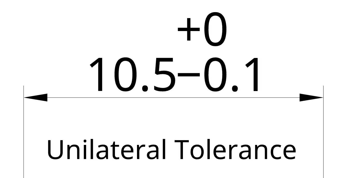
Allowed to vary in one direction only. Examples: 10.5 +0.2/-0.0 or 10.5 +0.0/-0.1
Limit dimensioning
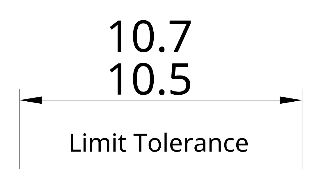
Specify the upper and lower size directly (no ±). Example: 10.3 – 10.7 is equivalent to 10.5 ± 0.2.
Single-limit tolerance (MIN / MAX)
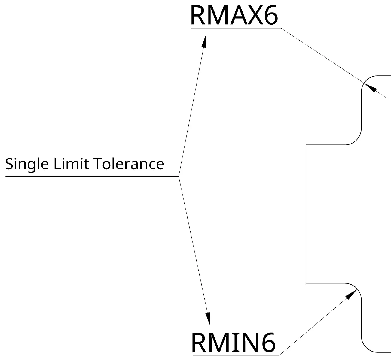
Used for features like chamfers, rounds, depths, thread lengths. Examples: R6 MIN (radius must be ≥ 6 mm), R6 MAX (radius must be ≤ 6 mm).
Reference & Theoretically Exact Dimensions
Reference dimension
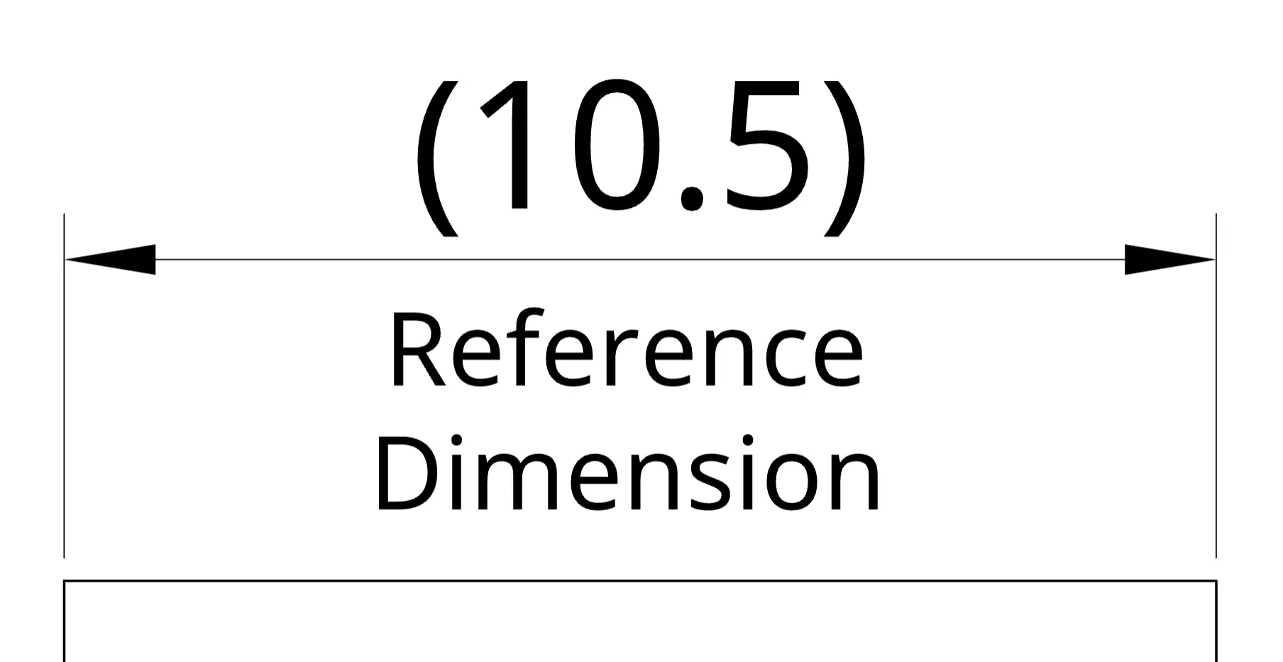
For information/visualization only—not controlled. Notation: parentheses or “REF” → (10.5), 10.5 REF.
Theoretically Exact Dimension (TED / Basic)
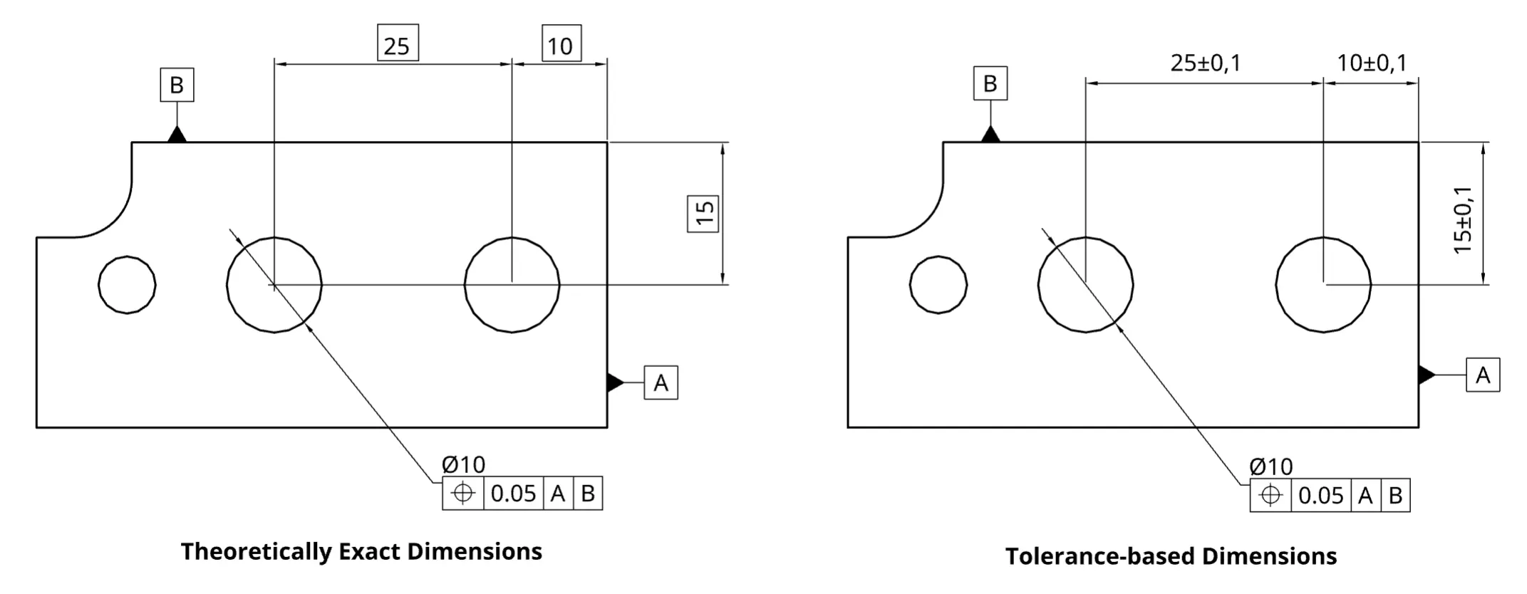
Used to avoid stack-ups. Shown in a rectangular frame; variation is controlled by GD&T, not by ±. Prefer datums + basic dims for true positional accuracy.
Approximate Dimension
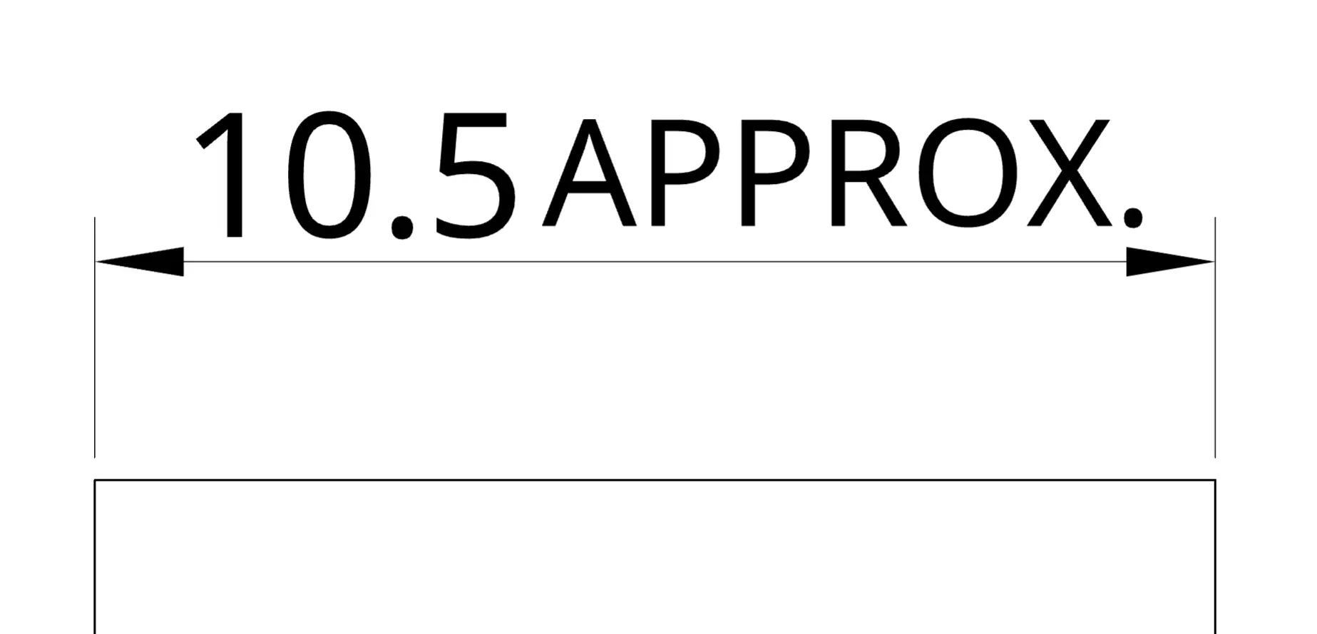
When precision is unimportant, show as approximate (no inspection). Notation: APPROX, ca., or ~ → e.g., ~10.5.
Practical Tips to Reduce Assembly Challenges
- Design to function: pick the loosest IT grade and fit that still meets performance.
- Avoid chain dimensions: use datums + basic (TED) + GD&T for critical features.
- Standardize: call out one ISO 2768 class; tighten only where it matters.
- Mind processes: grinding/honing can hit IT6–IT7; milling/turning favor IT8–IT10; as-cut/as-printed are looser.
- Check gauges: specify inspection method where tight fits matter (e.g., plug/ring gauges).
- Document intent: add a note for the target fit (e.g., “Ø12 H7/g6 sliding fit”).
How Werk24 Uses This
- Parses dimensional callouts, IT grades, and fit symbols (e.g.,
H7/g6,js7). - Normalizes tolerance styles (±, limit, unilateral) into numeric limit values.
- Computes clearance/interference envelopes for mating parts.
- Flags risks: missing general tolerance, inconsistent units, or potential stack-ups.