Measures (Dimensions): What You Need to Get Useful Parts
Dimensions ("Measures") describe the ideal sizes of features and—together with tolerances—the maximum allowed deviation before a part stops fitting or functioning.
Why this matters Parts can "look right" and still be useless if a single critical dimension is off. Correctly reading and normalizing dimensions prevents mismatches, rework, and scrap.
Werk24 reads the many styles that drafters use and returns one consistent, machine‑readable representation, independent of the drawing’s country, language, or personal drafting habits.
TL;DR
- There are several ways to place and orient dimensions. Werk24 detects the method and normalizes the output.
- We support linear, diameter (Ø), spherical diameter (SØ), chain, ascending/ordinate, angular, and chamfer dimensions.
- Outputs include units, feature references, anchors/bounding boxes, and confidence to enable review workflows.
- See also: Tolerances for allowed variation.
Dimensioning Methods
Drafters place dimension text according to house style and standards. Two common methods are defined in DIN 406‑11 and widely used globally.
Method 1 (mainly European)
Dimension text follows the two main reading directions: bottom‑up and left‑to‑right. This is prevalent across Europe.
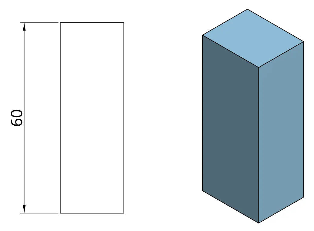
Method 2 (mainly US‑American)
Dimension text is oriented parallel to the title block, regardless of feature orientation. This is common in the United States.
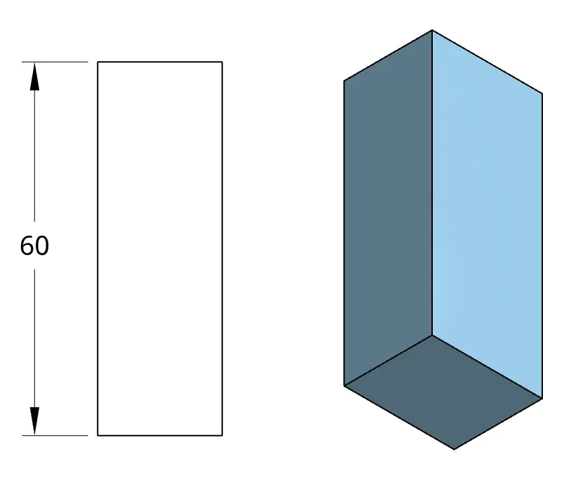
Good to know Werk24 detects the method automatically and returns consistent orientation and fields in the response.
Common Dimension Types
Diameter (Ø)
Diameter dimensions may be shown with a single leader/arrow and can reference internal or external features. Werk24 infers the most plausible target feature from context.
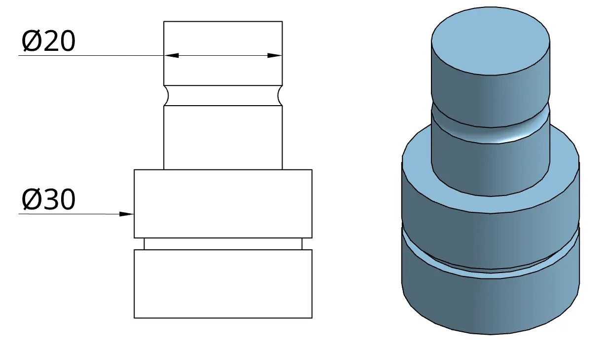
Spherical Diameter (SØ)
Use SØ to denote the diameter of a spherical surface. Example: SØ30 means a spherical diameter of 30 mm.
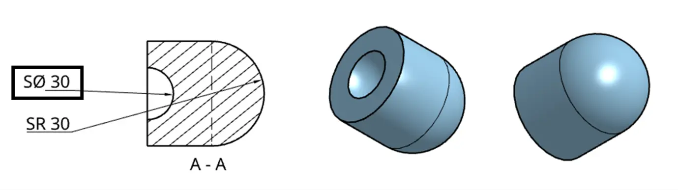
Chain Dimensions (Chaining)
Multiple adjacent dimensions share a common dimension line. Improves readability but stacks tolerances along the chain.
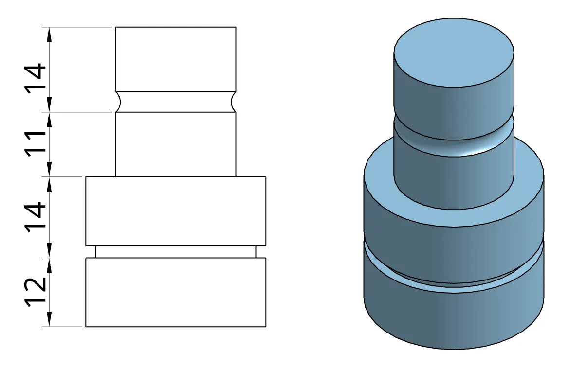
Tip Prefer ascending/ordinate dimensions over long chains for critical patterns to avoid tolerance build‑up.
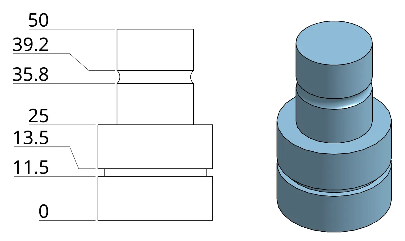
Ascending / Ordinate Dimensions
A single origin (datum) is defined; each feature is dimensioned by its distance from that origin—like a measuring tape. This minimizes accumulation of tolerances and is ideal for hole patterns and densely dimensioned areas.
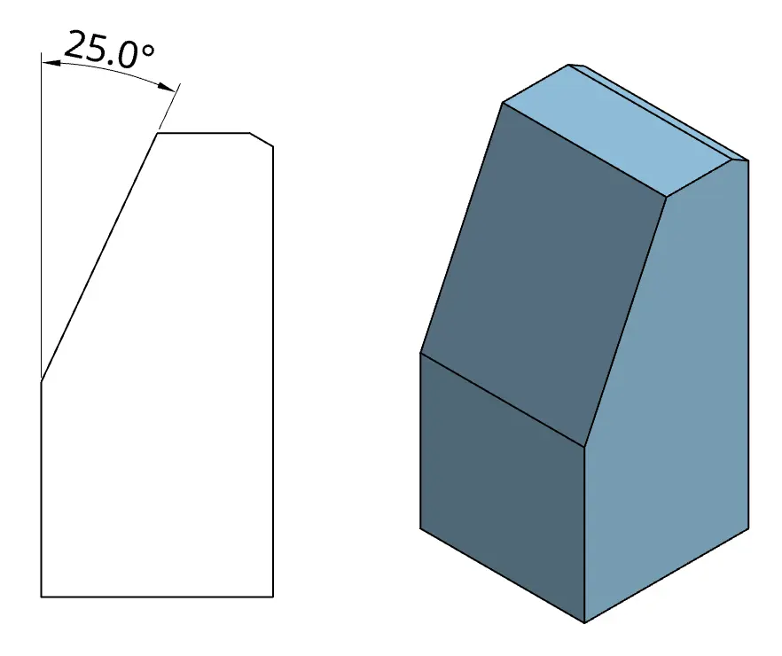
Angular Dimensions
Used to define the angle between edges or features. Shown via an arc centered at the angle’s vertex; may include tolerances (e.g., 30° ±0.5°).
Chamfer Dimensions
Chamfers are defined by width × angle (e.g., 1.0 × 30°). For the common 45° case, the shorthand C may be used with the width only (e.g., C2 means 2 mm at 45°).

Common Pitfalls & Checks
- Mixed methods on one sheet — Rare but seen on legacy drawings; Werk24 resolves per‑item context.
- Ambiguous leaders — Single‑arrow diameter callouts near multiple circles; we use spatial heuristics to choose the most likely target.
- Long chains — Watch for stacked tolerances; prefer ordinate patterns for functional groups.
- Missing units — We infer from title block/defaults but surface this for review if ambiguous.
- Chamfer shorthand —
Cimplies 45°. If your design needs a different angle, specify it explicitly.