Bends: Need to Know for Accurate Flat Patterns & Lower Cost
Bends describe how a flat sheet is formed into 3D. They are created by forming the material between tooling (e.g., V‑dies, punches) and are defined on drawings with bend lines, symbols, and notes.
Why it matters: Ambiguous bend notes lead to scrap, rework, and costly quoting errors. Clear bend specs give accurate flat patterns and consistent fit.
How to Read Bend Callouts
Common callouts combine direction, angle, and inside radius. Examples:
UP 90° R2→ bend upwards, 90° included angle, inside radius 2 mmDOWN 135° R1.5→ bend downwards, 135° included angle, inside radius 1.5 mm2X UP 90° R2 EQ SP→ two identical bends, equally spacedUP 45° R=t→ radius equals material thickness
Tip: State whether the angle is included (final angle between legs) or complementary (amount bent from flat). If not stated, assume included on Werk24.
Typical Elements on a Drawing
- Bend line: thin phantom/center line indicating where the bend starts.
- Arrow/leader: points to the bend with the callout.
- Direction:
UP/DOWNrelative to the principal plane (the reference surface from which bends are formed). - Quantity & order:
2X,BEND ORDER: 1‑2‑3when sequencing matters.
Core Bend Parameters
- Material thickness (t): nominal sheet thickness.
- Inside radius (R): final radius on the inside of the bend.
- Angle (θ): included angle unless otherwise specified.
- Neutral axis / K‑factor (K): location of the neutral axis during bending (K typically ~0.3–0.5 for air bending; depends on material and tooling).
- Bend allowance (BA): arc length of the neutral axis in the bend region.
- Setback (SB): distance the flange “consumes” due to bending.
- Bend deduction (BD): how much to subtract from the sum of flange lengths to get the flat length.
Reference formulas (for documentation):
BA = (π/180) × θ × (R + K × t)
SB = tan(θ/2) × (R + t)
BD = 2 × SB − BA
Note: Shops often use their own bend tables instead of the generic formulae. If you have vendor‑specific values (K, BA, BD), put them on the drawing or in a referenced standard.
Minimums, Distances & Good Practice (Design for Manufacturability)
- Inside radius: avoid “sharp” (R≈0) unless coining is specified; coining increases force, tool wear, and cracking risk.
- Flange length: ensure enough length to seat in the die. When in doubt, add a note: “Minimum flange length per vendor capability.”
- Holes/slots near bends: keep features away from the bend line to limit distortion; if close, add a note allowing post‑bend reaming or countersinking.
- Grain direction (rolling direction): bending perpendicular to grain reduces cracking; call it out on flat patterns if critical.
- Bend order: sequence can avoid collisions and improve accuracy; specify when required.
Reliefs & Transitions
Bend Relief
Small cut(s) at the ends of a bend to prevent tearing and surface pull. Typical styles:
- Rectangular relief — simple slit/slot at bend end (e.g.,
RELIEF 2×t × t). - Round/tear‑drop — reduces stress concentration.
Corner Relief
Local removal where multiple bends meet to avoid overlap/bulging in corners. Specify shape and size or reference a company standard.
Bend Transition / Facets
- Transition: the change from straight flange to radius.
- Facets: small flat segments approximating a curve in thin/adaptive features; acceptable if called out or controlled by a surface finish note.
Common Features Built from Bends
- Hems (open/closed): doubled material for stiffness and safe edges.
- Offsets (jogs): two opposite bends creating a step; specify offset height and leg lengths.
- Curls: rolled edge; specify curl diameter and gap.
- Louvres/embosses: formed features; often handled by a separate process note.
Tolerancing Bends
- Angle tolerance drives assembly fit; tighten only where necessary (e.g., ±1° vs ±0.25°).
- Radius tolerance affects flat‑pattern and fit with mating parts.
- Position of bend line may be controlled dimensionally or via a flat‑pattern tolerance.
- Reference related notes in Tolerances and GD&Ts.
What Werk24 Extracts From Bend Notes
Werk24 detects and normalizes:
- Direction (
UP/DOWN), angle, inside radius, quantity, order, equal spacing. - Explicit K‑factor, BA/BD, or a reference to a bend table/standard if present.
- Relief indications (bend/corner relief) and feature counts.
- Ambiguities (e.g., angle type not stated) are flagged to reduce false positives in downstream processes.
Examples (Callout Patterns)
UP 90° R2
DN 135° R1.5
2X UP 90° R2 EQ SP
UP 45° R=t
BEND ORDER: 1-2-3
UNFOLD PER K=0.40
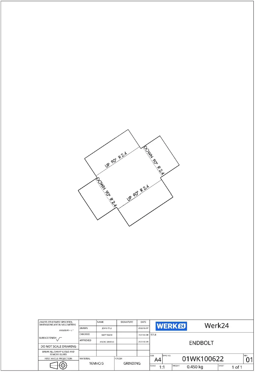
A technical drawing example with bends:
Glossary (Quick Reference)
- Included angle: final angle between flanges after bending.
- Complementary angle: the angle through which the sheet is bent from flat (180° − included angle).
- K‑factor: neutral axis distance from inside face divided by thickness.
- BA / BD: bend allowance / bend deduction used to compute flat patterns.